
UAV PROJECT
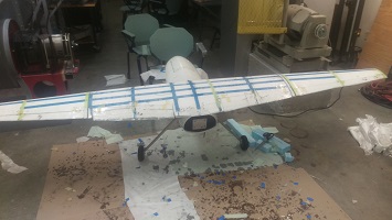
About The SponsorPainted Dog Research OrganizationLead Biologist: Greg Rasmussen |
Washington State UniversitySenior Design Project
Class: ME416
|
Problem Definition
The project's end goal was an autonomous flying UAV with a antenna payload that could track transmitting collars fitted on Painted Dogs in the Zimbabwe plains. Once the UAV connects with the collar (ground to air), data packets will be transferred to the UAV where it can be then uploaded to the Biologist's computer once the UAV's flight is complete. Data includes things like travel and behavioral patterns, pack to pack interaction, and even if the individual dog has been snared or killed by poachers. All of these things are pertinent to Greg Rasmussen's work and hopefully this project can make a real difference to not only this dwindling species but also many others around the globe.
Getting Started
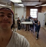
We started the project with research, having been given our parameters and slightly knowing the approximate scope of the payload we needed to hold, we wanted to be able to start our project with a good base.
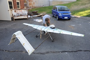
We looked at UAVs of many different builds. We ultimately decided to go with a V-Tail design with a push style motor, mid-mount, gas powered.
Calculations/Simulations
Once the base design was decided upon, proper calculations were made to ensure that the built product would actually fly.
This process may have been the most difficult one, due to the fact that exact payload weights and dimensions were only softly decided upon.
Ensuring that center of lift and center of gravity were in the spots that they needed to be proved to be difficult given the loose parameters. The team was able to get around this problem by implementing a variable payload distributer mounting rig out of Bosch Tubing. Flight analysis was done using xfoil and matlab while the plane was modelled using SolidWorks.
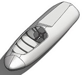
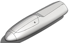
SolidWorks
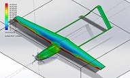
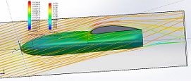
SolidWorks was very helpful in trying to get as accurate modelling numbers we could without having built the plane. The team had talked to another UAV group involved at WSU known as Genii headed by Doctor Jacob Leachman where they are using liquid hydrogen fuel supplying a proton exchange fuel cell and electric motor to fly. The Genii team gave us a lot of insight on the wet lay process, telling us what to do, what not to do, and most importantly that mistakes will be made, and the learning curve will be a journey to get through. The first thing we did then was weigh their access panel and divided by SA in order to find the specific weight of our plane (approx.). We then used this number in SolidWorks and figured the projected weight of the completed plane, adding in the motor, gas, and payload weights. This allowed for a pretty accurate center of gravity and center of lift calculation. Along with the weights and balances we were also able to do a fluid simulation, showing us things like concentrated drag spots and even lift properties.
Airfoil
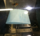
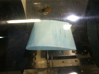
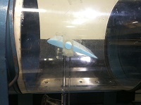
One of the major decisions that needed to be made was the type of airfoil the plane's wings were going to be modelled after. Myself and another engineer hotwired various airfoil configurations Clark Y, GOE412, NACA-0009 for testing. After mounting the airfoils in the wind tunnel shown in figure 5 and 6, we then tested various wind velocities and angles of attack, plotting both the corresponding lift and drag. We analyzed the data and decided that with our given boundaries (take-off/landing distances, cruising altitude, banking/turning radius) we concluded that GOE412 would be the best option.
Building the UAV
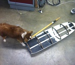
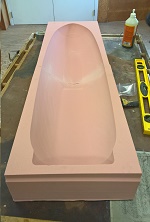
After deciding on the fuselage geometry, the team created a negative mold from dense insulation foam. By first stacking and gluing multiple layers, a Z-dimension was created, then a CNC machine was used to cut the negative dimensions [Figure
7]. The mold was separated by the top and the bottom half. Once the molds were complete, they were then sprayed down with duracoat to create a smooth, airtight, releasable surface for the composites.
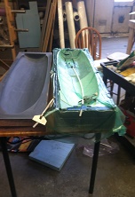
Using a mixture of carbon fiber and fiber glass composites, the team used wet-lay techniques - consisting of laying down the composite, liberally applying epoxy, and then wrapping with plastic to create airtight seal for vacuuming [Figure 8]. The epoxy used was a mixed solution that heated upon contact which allowed for drying without the use of an oven. After giving ample time for the fuselage to harden and dry, it was then pried out of the mold and squared off to create straight contact edges.
Structure
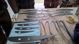
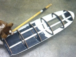
To reinforce the structure, the team sectioned off portions in which bulkheads would be glued into place. The inside dimensions were taken from the model and carbon fiber honeycomb was waterjet to fit. In a similar suit, wood bulkheads for the wing were created using the same waterjet technique. Some specialty parts for the fuselage and the wing alike were 3D-printed in house from Solidwork-built models.
Internals
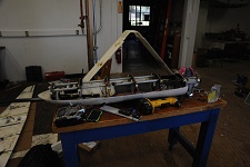
The internals and the payload were tough to fit, so to speak. Like previously stated the weights were not concrete, which made it difficult to map out the placement and therefore the mounts. The gas tank, being variably weighted over flight time, had to be placed at the center of gravity so that shifts in moment were kept to a minimum. With the engine being mounted in the back, it left the weights of the payload to be placed in front of the CoG and CoL, but to what extent? The team decided to use Bosch Tubing as a rail mount for the payload so that way the weight could be shifted and the moment on the plane could be easily altered at any point while the UAV is grounded. The tubing was cut to size and glued into the bulkheads, running two parallel bars from the front of the fuselage up to the last bulkhead, and one from the middle bulkhead and butted up against the back frame on the opposite side as the double run, shown in figure [12].
Top rails are to support the payload/gas tank while the bottom rail mounts the engine throttle servo and the back end of the gas tank.
Propulsion
Our initial thought on propulsion was to go with a battery powered engine, since this type of motor is something many of us were familiar with. This idea got thrown out real soon once the flight goals were set. Gas was the only way to keep the plane in the air for as long as we needed, and its ability to refuel is so much greater than charging/replacing batteries. This lead to researching many different types of gas powered engines. The biggest factor was the weight of the plane and the weight of the rear mounted engine. After much analysis the team and I decided to go with Saito FG-40. The weight balance vs power output were both within acceptable ranges.
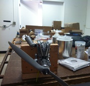
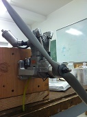
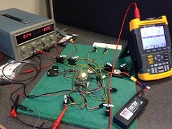
Breaking in the engine was most important, but relatively easy. We mounted the engine on a test block that was then attached to a static table. We ran the engine rich and adjusted the carburetor to hit the right mixture. We attached the tachometer to a Data Acquisition Unit where we then compared fuel consumption to rotations of the prop. With this information we were able to find our most efficient speed for the plane to travel, elongating flight distance while keeping constant the fuel tank.
Without a doubt the hardest part relating to propulsion was mounting the engine. We needed to create a way of mounting sturdy to the rear wall without making the whole thing vibrate. Vibrations were going to be kept to a minimum by balancing the prop best we could, but no system is perfect. What really made us nervous was the fear that the engine would start to vibrate at a frequency that would make the system oscillate heavily. This could cause catastrophic damage to the frame and could even cause our plane to fall from the sky. To minimize this risk we bolted the engine on spring and damper mounts, keeping it stiff with a little give.